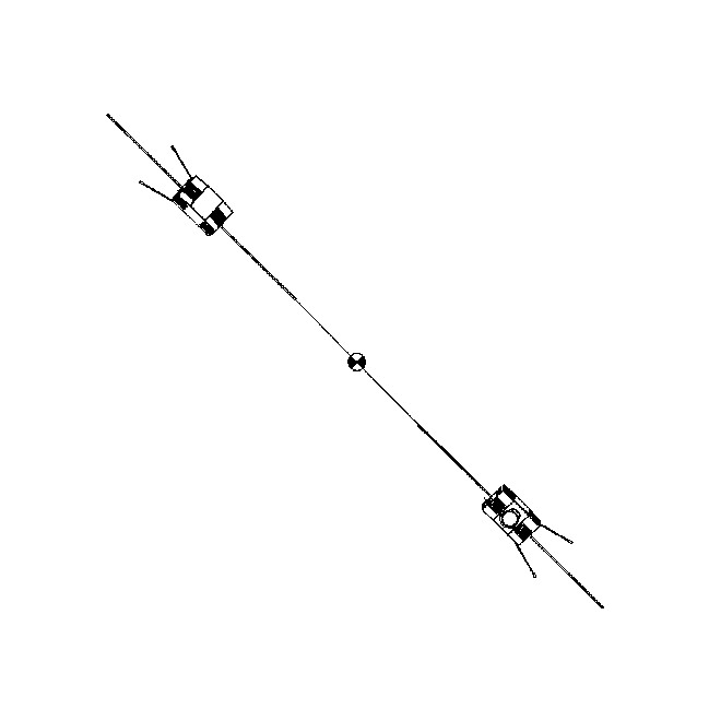
BOLAS spacecraft in final deloyed configuration.
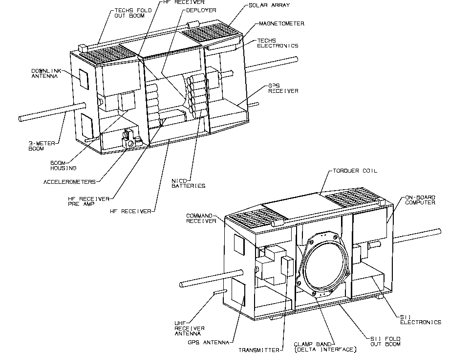
The layout of the subsatellites is shown in the figure below (note only BOLAS-1 is shown). The overall configuration is driven by the accommodation requirements for the Delta II launch vehicle. Note that the tether from the tether deployer (and similarly from the retriever on BOLAS-2) goes through the boom package and out the tip of the boom. This ensures the booms are aligned with the tether and avoids the possibility of the tether getting tangled around the boom. It also helps to stabilize the payload oscillations relative to the tether. The concept uses two individual BI-STEM boom packages from Astro Aerospace, each deploying a single element, as these allow for easily feeding the tether through the back of the boom package and out the tip of the boom when stowed and when deployed. This type of boom was flown on OEDIPUS-C. As the payloads will be stabilized by the tether tension with damping provided by the BI-STEM booms, subsatellite attitude control about the orthogonal axes to the tether is not required. However, primarily for thermal reasons, a magnetic torque coil is provided to allow for some intermittent open loop control (via the ground) about the tether axis to ensure sufficient spin so that the solar energy can be equally distributed around all sides. Full 3-axis attitude determination will be provided by the magnetometer via processing on the ground. The accelerometers will be used to provide accurate attitude rate information and also to determine the tether tension.

Layout of one subsatellite (BOLAS-1).
The power system consists of two small solar arrays (each made up of 45 2 x 4 cm Si cells) mounted on each face of the subsatellite (except the ends), a 4.5 A-hr battery made up of commercial NiCd D-cells, and a Power Distribution Unit (PDU) and DC-DC converters used to provide switchable power to the instrument and subsystems. The pair of solar arrays on each face provide nominally 28 V which will supply the necessary power in any arbitrary orientation of the two-body system and at all orbital Equator crossing times.
The on-board computer (OBC) consists of a processor card, an I/O card, a data handling card, and 4 mass memory cards. It decodes commands from the command receiver, executes real-time and time-line commands, collects science and housekeeping data, provides 64 Mbytes of on-board storage, and outputs a 2 Mbps serial bit stream to the telemetry transmitter. Low power is a prime requirement and a 80C186 processor has been selected for the baseline concept as it has adequate capability at very low power and has considerable space flight heritage.
The GPS receivers will probably be modified versions of the TurboStar units from Allen Osborne Associates, Inc. This unit provides the necessary features including dual frequency capability and sufficient on-board processing to allow arbitrarily selecting up to 8 GPS satellites. It has been used in space and is being implemented in a number of smallsat and microsat missions including the GPS/MET|MicroLab-1 mission by Orbital Sciences Corp., NASA's WakeShield facility, the Danish Oersted microsatellite, and others. The units require minor modifications to provide a clean 5 MHz reference signal that will be used by the HF receiver for synchronization between the signals received from BOLAS-1 and 2 via ground processing (currently the reference signal is corrected by the GPS clock once every second).
The baseline downlink transmitter is an Aydin Vector T-100S/L Series S-Band 2 Watt RF Telemetry Transmitter which has been used on the FREJA mission and accepts binary bits and produces a Linear or Binary Phase modulated carrier. Two Aydin Vector RCC-100 Series UHF Command Control receivers are planned where each connects to a small UHF dipole antenna located at each end of the subsatellite. Both receivers will be on continuously (although strobed to minimize power requirements) so that a command can be received in almost any orientation of the two-body system.
The GPS and transmitter antennas are microstrip patches that are located on each end of the subsatellite as shown in the figure above. The GPS antennas (L-band) will be designed for this mission to provide a nearly omni-pattern. The two S-band antennas for the transmitter can be switched via timeline commands so that only one is used at a given time when it is oriented towards the ground.
Spacecraft Mission Specifications
Mass:
- approximately 72 kg (BOLAS-1)
- approximately 70 kg (BOLAS-2)
Power consumption (peak):
- approximately 77 W (BOLAS-1)
- approximately 85 W (BOLAS-2)
Dimensions:
- ?? x ?? x ??
Orbit parameters:
- inclination: 102.81 degrees
- perigee: 350 km
- apogee: 800 km
- period: 90.020 minutes
- e: 0.0324
- perigee drift rate: -2.794 degrees/day
- right ascension drift rate: 0.657 degrees/day
- inclination drift rate: 0 degrees/day
Mission duration:
- approximately 6 months
Launch
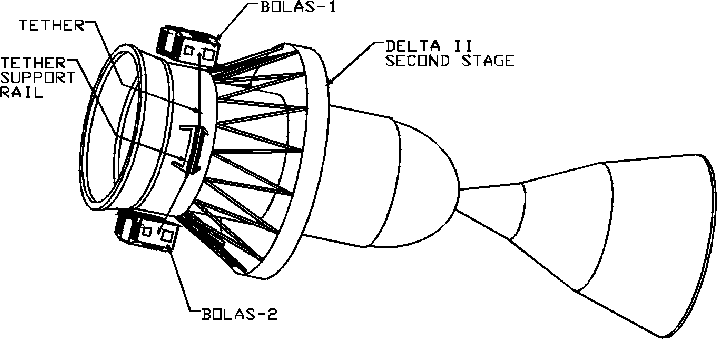
NASA will endeavour to provide the launch and support integration of the spacecraft on a Delta II second stage. The current proposed baseline for launch as a secondary payload is with the Radarsat II mission, presently planned to be launched in the fourth quarter of 2001. The BOLAS as a secondary payload would be manifested inside the same fairing envelope as the primary spacecraft on the Delta II vehicle as shown in the figure below.

BOLAS Subsatellites Integrated on Delta II Second Stage.
Immediately after deployment of the Radarsat II spacecraft, the Delta II second stage and the attached BOLAS spacecraft will be in the Radarsat II orbit, i.e. a circular orbit with 800 km altitude, and sun-synchronous with dawn-dusk orientation. Launch will be from Vandenberg AFB and the ascending node would cross the equator at 1800 hr PST. The inclination would be 98.64 degrees and its orbital period 100.7 minutes.
When the primary science data is taken, the satellite will be passing through the auroral oval at low height. Both daylight and darkness passes are required over the course of the mission. The requirements can be satisfied with an orbit with perigee and apogee of 350 km and 600 km respectively, and a drift over the course of the mission from an initial dawn-dusk orientation through to and beyond a noon-midnight orientation. As well the perigee is planned to be near the auroral oval during the main period of science measurements. The BOLAS orbit will be achieved with the Delta II second stage after deployment of Radarsat II with most probably a two impulse orbit transfer strategy.
Payload
Detailed descriptions of the scientific instrumentation can be found on the Mission Payload page.
- HF Receiver
The HF Receiver is a broadband receiver for measuring wave fields from both manmade and spontaneous sources. Basically it has a preamplifier that matches the high impedance of the BOLAS dipoles to the 50-ohm input of the receiver signal processor. The latter comprises two branches. One is for direct amplification at frequencies up to 50 kHz. The other is a double heterodyne for frequencies between 100 kHz and 20 MHz, at 50 kHz steps. The receiver has considerable heritage from the OEDIPUS-C REX receiver.
- Suprathermal Ion Instrument (SII)
The Suprathermal Ion Instrument (SII) images the 2-D ion distribution from 0-50 eV, and provides an integral measure of ion flux at rates sufficient to resolve localized ion heating structures on spatial scales of tens of meters. The SII is based on the design of the Freja Cold Plasma Analyzer, with two major modifications: the dimensions will be shrunk by a factor of roughly 3, and the detector design will be based on a charge-coupled device (CCD), not a network of charge amplifiers.
- Thermal Electron Capped Hemisphere Spectrometer (TECHS)
The Thermal Electron Capped Hemisphere Spectrometer (TECHS) is an azimuthal imaging tophat electrostatic analyzer. By sweeping the analyzer voltage, TECHS measures a count rate that can be directly related to the distribution function of low energy and thermal electrons. From these measurements, integral moments of the electron distribution function, including density, anisotropic temperature, bulk drift, and heat flux may be derived. A version of the instrument flew successfully on the SCIFER sounding rocket. Similarly to the SII, the TECHS sensor also mounts on the end of a 1 m boom.
- Global Positioning System (GPS) receiver
The GPS receiver collects L-band signals from the GPS satellite constellation to determine precise time, position and velocity. By determining the excess phase of measurements to GPS satellite signals that are being occulted by the earth's atmosphere, electron density profiles can be obtained (among other products). The Allen Osborne Associates, Inc. TurboStar receiver is the planned baseline receiver.

BOLAS spacecraft in final deloyed configuration.

Layout of one subsatellite (BOLAS-1).
- approximately 72 kg (BOLAS-1)
- approximately 70 kg (BOLAS-2)
- approximately 77 W (BOLAS-1)
- approximately 85 W (BOLAS-2)
- ?? x ?? x ??
- inclination: 102.81 degrees
- perigee: 350 km
- apogee: 800 km
- period: 90.020 minutes
- e: 0.0324
- perigee drift rate: -2.794 degrees/day
- right ascension drift rate: 0.657 degrees/day
- inclination drift rate: 0 degrees/day
- approximately 6 months
Launch
NASA will endeavour to provide the launch and support integration of the spacecraft on a Delta II second stage. The current proposed baseline for launch as a secondary payload is with the Radarsat II mission, presently planned to be launched in the fourth quarter of 2001. The BOLAS as a secondary payload would be manifested inside the same fairing envelope as the primary spacecraft on the Delta II vehicle as shown in the figure below.

BOLAS Subsatellites Integrated on Delta II Second Stage.
Immediately after deployment of the Radarsat II spacecraft, the Delta II second stage and the attached BOLAS spacecraft will be in the Radarsat II orbit, i.e. a circular orbit with 800 km altitude, and sun-synchronous with dawn-dusk orientation. Launch will be from Vandenberg AFB and the ascending node would cross the equator at 1800 hr PST. The inclination would be 98.64 degrees and its orbital period 100.7 minutes.
When the primary science data is taken, the satellite will be passing through the auroral oval at low height. Both daylight and darkness passes are required over the course of the mission. The requirements can be satisfied with an orbit with perigee and apogee of 350 km and 600 km respectively, and a drift over the course of the mission from an initial dawn-dusk orientation through to and beyond a noon-midnight orientation. As well the perigee is planned to be near the auroral oval during the main period of science measurements. The BOLAS orbit will be achieved with the Delta II second stage after deployment of Radarsat II with most probably a two impulse orbit transfer strategy.
Payload
Detailed descriptions of the scientific instrumentation can be found on the Mission Payload page.
- HF Receiver
The HF Receiver is a broadband receiver for measuring wave fields from both manmade and spontaneous sources. Basically it has a preamplifier that matches the high impedance of the BOLAS dipoles to the 50-ohm input of the receiver signal processor. The latter comprises two branches. One is for direct amplification at frequencies up to 50 kHz. The other is a double heterodyne for frequencies between 100 kHz and 20 MHz, at 50 kHz steps. The receiver has considerable heritage from the OEDIPUS-C REX receiver.
- Suprathermal Ion Instrument (SII)
The Suprathermal Ion Instrument (SII) images the 2-D ion distribution from 0-50 eV, and provides an integral measure of ion flux at rates sufficient to resolve localized ion heating structures on spatial scales of tens of meters. The SII is based on the design of the Freja Cold Plasma Analyzer, with two major modifications: the dimensions will be shrunk by a factor of roughly 3, and the detector design will be based on a charge-coupled device (CCD), not a network of charge amplifiers.
- Thermal Electron Capped Hemisphere Spectrometer (TECHS)
The Thermal Electron Capped Hemisphere Spectrometer (TECHS) is an azimuthal imaging tophat electrostatic analyzer. By sweeping the analyzer voltage, TECHS measures a count rate that can be directly related to the distribution function of low energy and thermal electrons. From these measurements, integral moments of the electron distribution function, including density, anisotropic temperature, bulk drift, and heat flux may be derived. A version of the instrument flew successfully on the SCIFER sounding rocket. Similarly to the SII, the TECHS sensor also mounts on the end of a 1 m boom.
- Global Positioning System (GPS) receiver
The GPS receiver collects L-band signals from the GPS satellite constellation to determine precise time, position and velocity. By determining the excess phase of measurements to GPS satellite signals that are being occulted by the earth's atmosphere, electron density profiles can be obtained (among other products). The Allen Osborne Associates, Inc. TurboStar receiver is the planned baseline receiver.